Simple Introduction to Computer Network and the Internet
Get 1000000 0FP0EXP Token to remove widget entirely!
Get 500000 0FP0EXP Token to remove my NFTS advertisements!
Table of Contents
- 0. Outline
- 1. A tour around todays Network
- 2. A Computer Network
- 3. Simple Routing
- 4. Common Features on The Internet
0. Outline
This topic would like to show you from afar what a computer network looks like. We won’t show you deep inside because that’s where things tends to get difficult, for example subnets, network traffic, protocols, etc. Simply we want to Introduce what is the computer network, how today’s people rely on it now, and how is it even or how we are able to use it. From afar The Internet looks complicated as on Figure A, but to explain it simply it’s a connection of so many nodes consist of computer, servers, and other networking devices.
Figure A. Internet Illustrated https://www.andrew.cmu.edu/user/pcarboni/internet_history_site
Objective
If some stranger asked you of what is The Internet and you can answer simply, then you got the gist of this course. If you can find the puzzle pieces and form the picture of The Internet puzzle, then you have fulfilled the learning objective of this course. For now we would like to list the following learning objective. Simulate Local Area Network (LAN). Simulate Wide Area Network (WAN). Common services of The Internet. Design your simple cloud (Figure B for example).
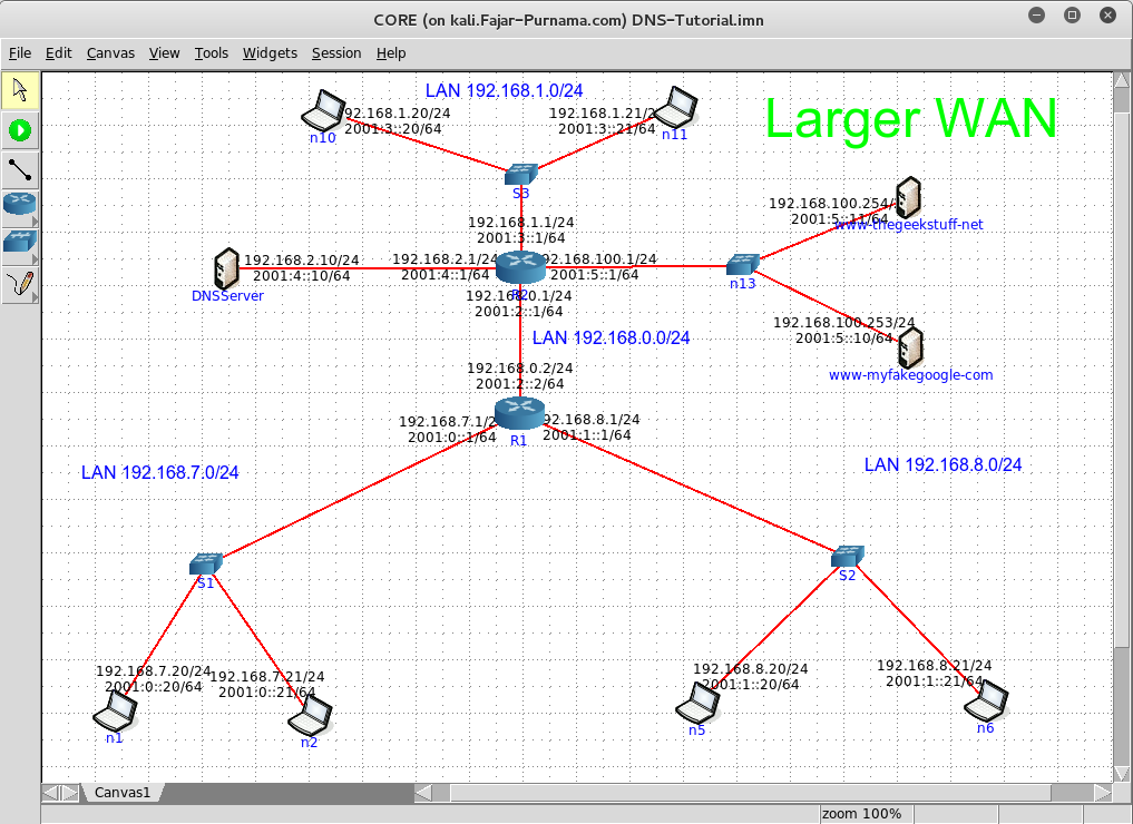
Figure B. Sample Network Simulation
Simulation Environment
If you have the hardwares to perform your experiment it’s very suggested to make use of them, but here we will give the materials in simulations. My experiences in network simulators is that I found Cisco Packet Tracer the easiest to use (very recommended for beginners), but to obtain this software legally you need to enroll into Cisco Academy. We understand that not all have access to this software, so we decided to use alternatives. If you have a legal Cisco IOS image Gui Network Simulator 3 (GNS3) is your next alternative, if not then search for other free network simulator. Here we use Common Open Research Emulator (Core) Network http://www.nrl.navy.mil/itd/ncs/products/core.
1. A tour around todays Network
1.1 Definition
This contains two words “computer” and “network” is a connection of computer devices in order to exchange data with each others refer to Figure 1.1. It doesn’t matter how it is connected or what it is connected, whether we are using wired like serial cable, UTP, fiber optic, and usb, or wireless for as long as it’s connected it is a computer network. A computer network is not limited to private computers (PCs), computer devices such as gadgets, mobile phones, printers, and gaming consoles are counted into computer network. The place where these devices interact with each other is the computer network.
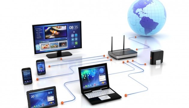
Figure 1.1 Illustration of simple computer network
1.2 The Internet
On the previous Figure 1.1 there are lots of device connected and one Earth like planet. The Earth like planet is a very large network and who knows how much is inside, so we just referred it to The Internet. The Internet contains connection of computer devices around the world. The Google server which was first in Standford University, now had many server distributed around the world. It also goes for Yahoo and MSN. Facebook is in United State, Line is in Japan, and if you’re accessing this course through Moodle cloud, the head quarter (HQ) is in Australia. They made these sites publicly available on the network called The Internet. There are many stuffs available thanks to The Internet, following are examples:
Search Engines on Figure 1.2.
Figure 1.2 Google
Wikis on Figure 1.3.
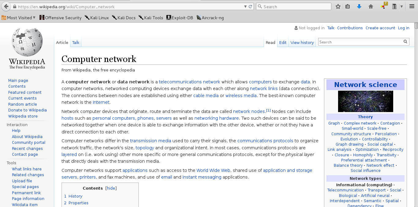
Figure 1.3 Wikipedia
Social Medias on Figure 1.4.
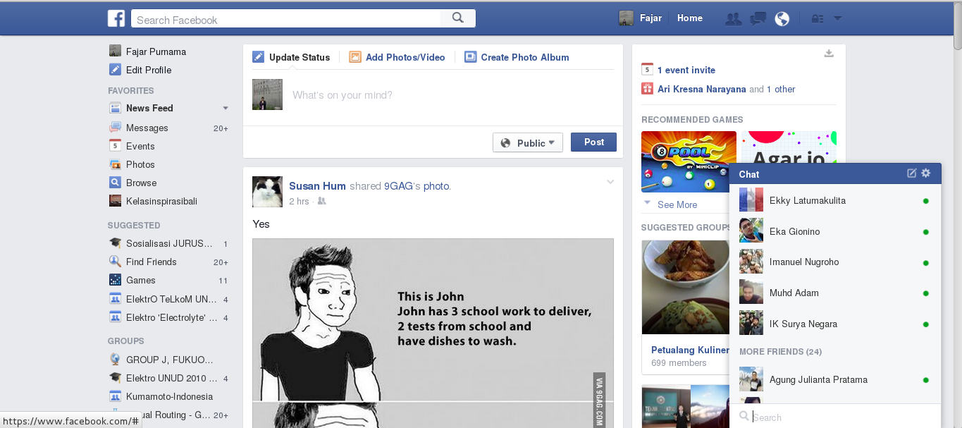
Figure 1.4 Facebook
Online Videos on Figure 1.5.

Figure 1.5 Youtube
Online Courses on Figure 1.6.

Figure 1.6 Coursera
Online Games on Figure 1.7.
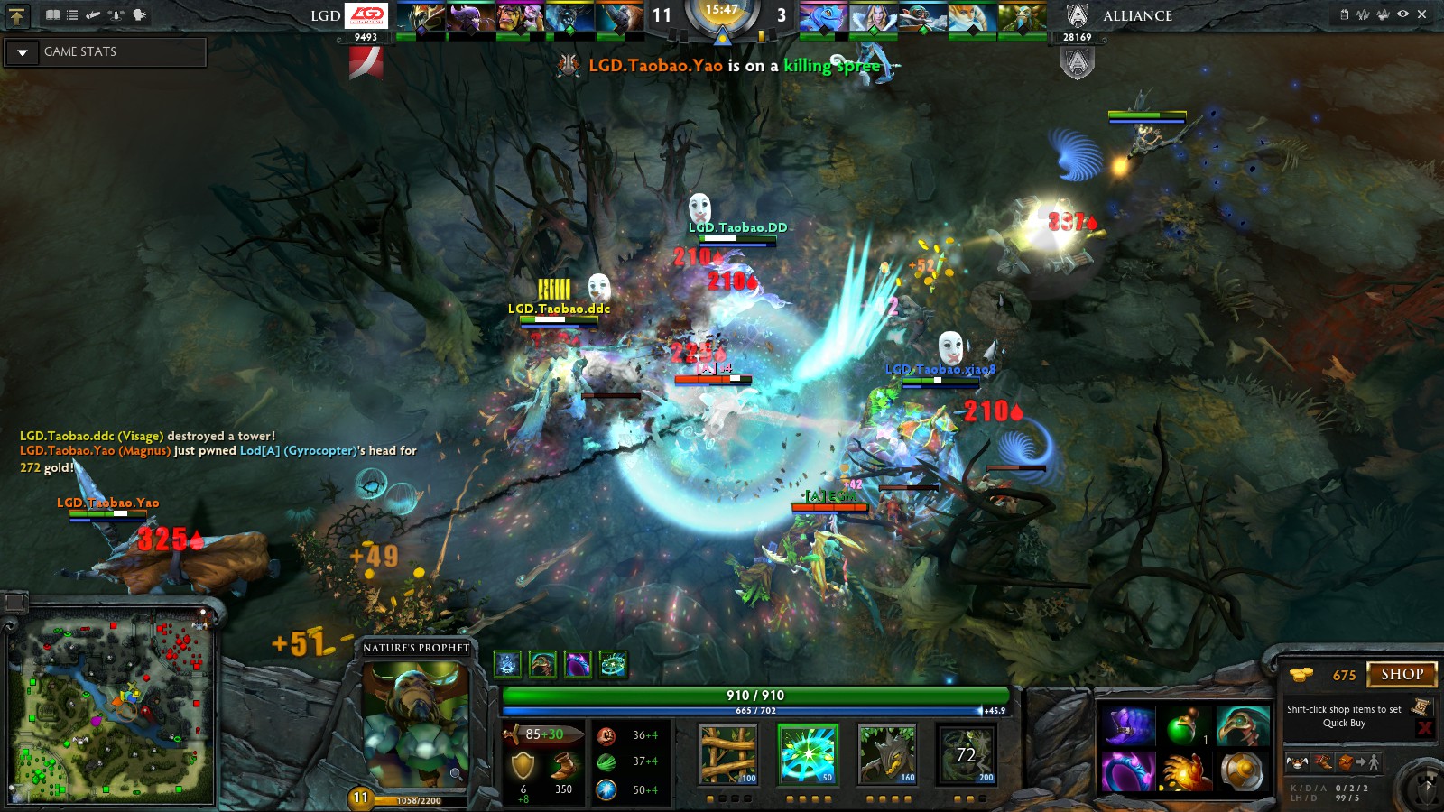
Figure 1.7 Dota2
Personal Websites (blogs) on Figure 1.8.
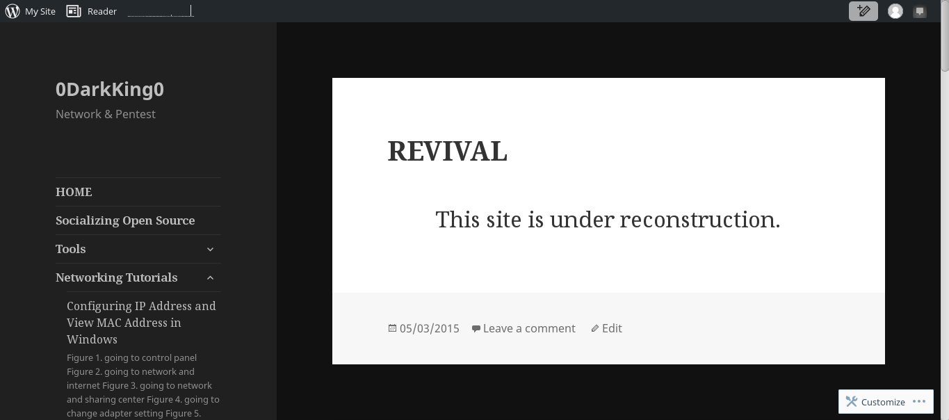
Figure 1.8 Wordpress
Emails and Chats on Figure 1.9.
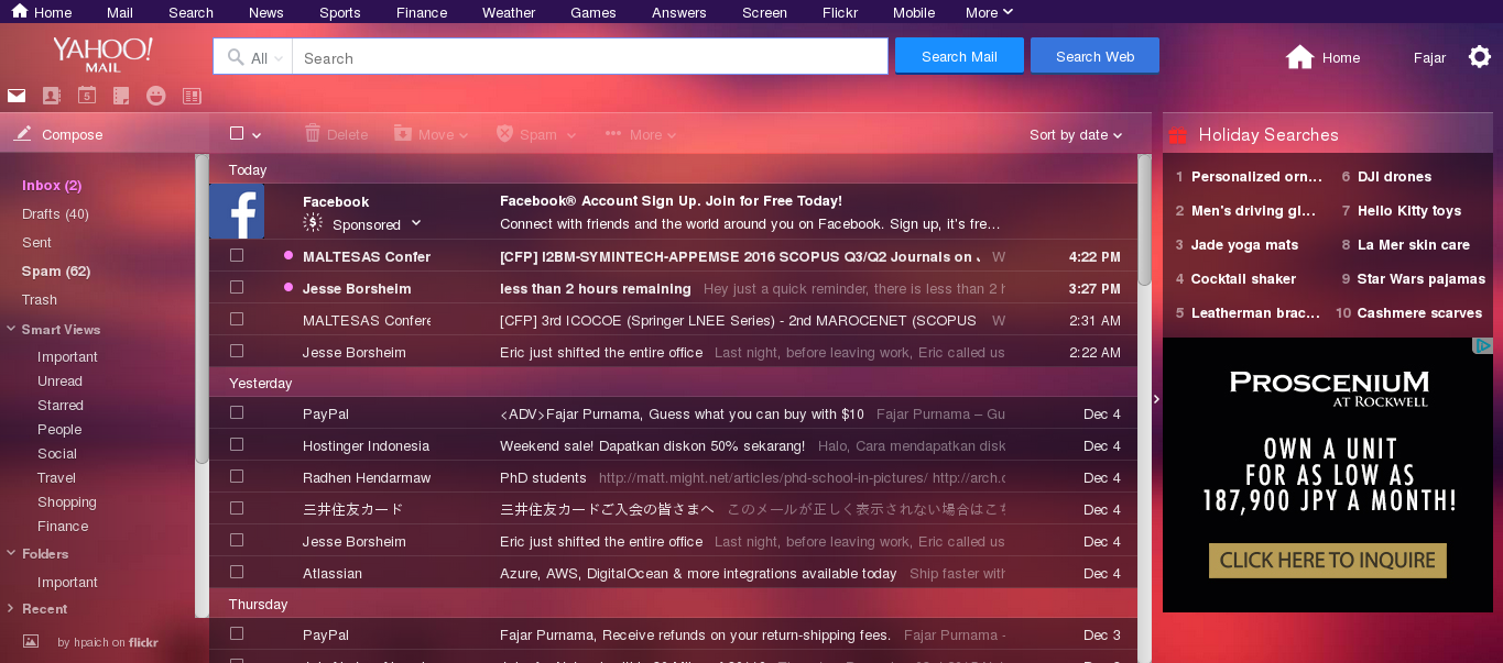
Figure 1.9 Yahoo Mail
Cloud Services on Figure 1.10.
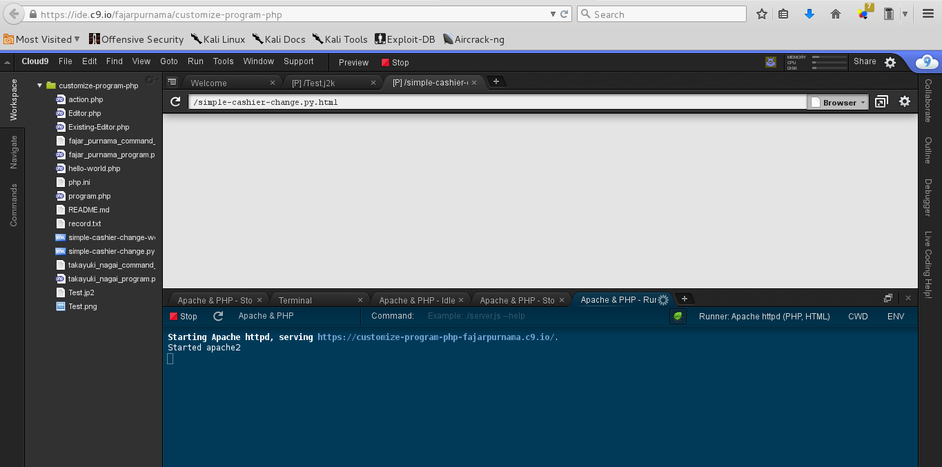
Figure 1.10 Cloud9
2. A Computer Network
2.1 Types of Computer Network
Figure 2.1 is a summary of this topic.
Figure 2.1 Types of Computer Network Summary
2.1.1 Peer-Peer (P2P) Network
A peer to peer network is a network consist of only 2 device, whether it is wired or wireless. It’s like a conversation between 2 people on Figure 2.2.
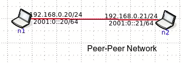
Figure 2.2 Peer-Peer Network
2.1.2 Local Area Network (LAN)
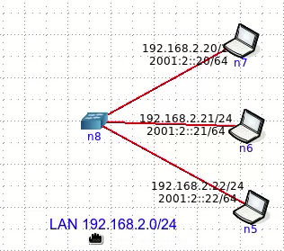
When another device joins with peer-peer network, it then becomes a local area network (LAN). A LAN consist of more than 2 device that can be connected through a bus cable, a layer 1 Hub, or a layer 2 switch. For this course we just show the simple part on Figure 2.3 is a LAN consist of PCs connected to a L2 switch.
.png)
Figure 2.3 Local Area Network (LAN)
Wide Area Network (WAN)
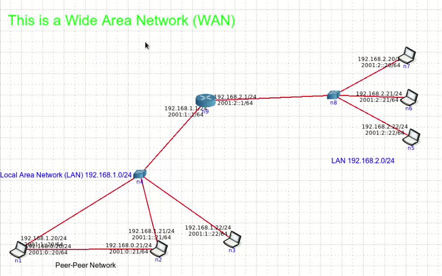
A wide area network (WAN) is network consist of 2 or more LAN which definitely larger than a peer-peer network and a LAN. It is said that The Internet is the largest WAN. On Figure 2.4 shows a minimal WAN consist of of 2 LAN where they are connected by a L3 router.
.png)
Figure 2.4 Wide Area Network (WAN)
2.2 Some Information
2.2.1 Internet Protocol Version 4
Each computer devices has 2 commonly known address. One is a hardware address (usually MAC: e0:3f:49:c3:36:dc) and network address which today use internet protocol version 4 (IPv4) and in the future will implement IPV6. The hardware address we judge as a later topic so we will only explain the correlation between hardware address and network address is they synchronize by a process called network address translation (NAT).
Today we still use IPv4 address to connect to the network. The IP address for example 192.168.0.2/24 or 192.168.0.2 255.255.255.0 is not on the computer itself, but assigned on the network interface (cable ethernet adapter, wireless adapter, etc). The last part of the IP address (192.168.0.24/24, or 192.168.0.24 255.255.255.0) is the subnet mask which the determines the networks it belongs to. On the network:
- The first IP address is a network address.
- The second IP address is usually assigned on the default gateway.
- The last IP address is the broadcast address.
- The remaining IP address is assigned to other devices or each PCs.
The subnet mask determines the class of the IP address. Class A network can store more IP address, class B is less than class A, and class C is the least. There are also classless IP address based on subnet mask, but it’s regarded as advance topic, so it will not be discuss here. Here we only use class C private IP address from 192.168.0.0 - 192.168.255.255.
| Class | Subnet | Total address |
|---|---|---|
| A | 255.0.0.0 or /8 | 16277215 |
| B | 255.255.0.0 or /16 | 65535 |
| C | 255.255.255.0 /24 | 255 |
After an IP address there is a slash (/) indicating the subnet mask based on the number of binary “1” containing on the subnet mask when converted to binary value. That’s also advance topic but we would like you to remember the following:
| 255.0.0.0 | /8 |
|---|---|
| 255.255.0.0 | /16 |
| 255.255.255.0 | /24 |
You may write it like this 192.168.1.1/24 or 192.168.1.1 255.255.255.0. By the way a private IP address is an address we can use on the network outside The Internet and public IP address are other than private address that are registered on The Internet.
| Class | Private IP Address |
|---|---|
| A | 10.0.0.0/8 |
| B | 172.16.0.0/16 |
| C | 192.168.0.0/24 - 192.168.255.0/24 |
We will only be using class C private IP address. Back on the topic of network address, default gateway, broadcast address, and host address examples as follow:
| Subnet Mask | Network ID | Default Gateway | Host ID (Free Address) | Broadcast ID |
|---|---|---|---|---|
| 255.255.255.0 or /24 | 192.168.0.0 | 192.168.0.1 | 192.168.0.2 - 192.168.0.254 | 192.168.0.255 |
| 255.255.255.0 or /24 | 192.168.1.0 | 192.168.1.1 | 192.168.1.2 - 192.168.1.254 | 192.168.1.255 |
| 255.255.0.0 or /16 | 172.16.0.0 | 172.16.0.1 | 172.16.0.2 - 172.16.255.254 | 172.16.255.255 |
| 255.0.0.0 or /8 | 10.0.0.0 | 10.0.0.1 | 10.0.0.2 - 10.255.255.254 | 10.255.255.255 |
If you return to section 2.1 of an IP address assign, for example 192.168.1.20/24 belongs to network 192.168.1.0, and 192.168.2.20/24 belongs to network 192.168.2.0.
2.2.2 Open Systems Interconnection Model
he Open Systems Interconnection had 7 layers or referred as OSI layer which a network technician must have heard at least once on Figure 2.5.
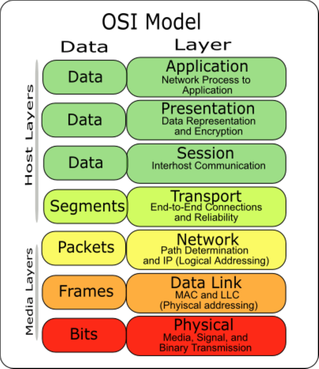
Figure 2.5 Osi Layer https://commons.wikimedia.org/wiki/File:Osi-model-7-layers.png
It’s also an advance topic so we cover only the outline. L1 Physical is on the physical transmission media site like the ethernet cable, fiber optic, or radio wave. L2 Data Link is on the hardware address MAC for example, this layer groups the bits received in transmission. L3 Network is on the network address, IP address for example and defines the routing mechanism. L4 Transport is the transport mechanism use, TCP or UDP for example. L5 Session creates a session. L6 Presentation and L7 Application is what we see on the screen, interfaces the we directly interact with.
3. Simple Routing
3.1 Default Gateway
On our PCs on everyday life we at least have 4 configuration that we need set which are (1) IP address (2) Subnet Mask (3) Default Gateway (4) Dns Server, as on Figure 3.1.
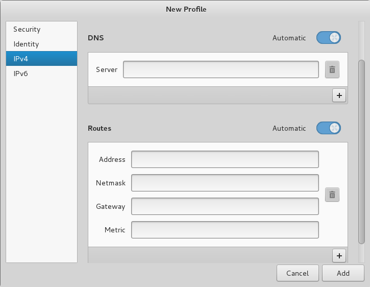
Figure 3.1 Common PC network configuration
If on the previous assignment you were using Core Network to simulate a simple WAN, the default gateway or route on each PCs are automatically set (also the IP address on the PCs and Router). What if we’re on the situation to set it manually? Considering we have a PC and want to connect to the Internet on an available network that gives access to The Internet. Roughly a peer said “you may connect to our switch, our network is 192.168.7.0/24, and the router’s inside IP address is 192.168.7.1/24, (psssst, for DNS just use Google’s for now)”. With that information we configure our PC as example on Figure 3.2:
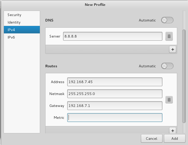
Figure 3.2 Filled Manual Host Network Configuration
Now what is a default gateway? On this configuration a default gateway is the gate we go through to connect to another network, or a door to get out of our network. On our PC’s configuration is the door to connect to The Internet. We can illustrate this as house, our house had many rooms with each room has its own address. Where do we go to go to another house? The answer is the “front door” which is equivalent to the “default gateway”.
Next let’s try connecting 2 LANs and manually configuring them. Say the previous network is 192.168.7.0/24 and we want to connect it to a neighbor network of 192.168.8.0/24. It’s best we generate a table as in section 2, then to test whether we can go to our neighbor using “trace route” command on Figure 3.3. From 192.168.7.20/24 To reach the neighboring network first must go through the interface of router that has the address of 192.168.7.1/24 (default gateway), then it reaches the destination 192.168.8.20/24.
| Subnet Mask | Network ID | Default Gateway | Host ID | Broadcast ID |
|---|---|---|---|---|
| 255.255.255.0 or /24 | 192.168.7.0 | 192.168.7.1 | 192.168.7.2 - 192.168.7.254 | 192.168.7.255 |
| 255.255.255.0 or /24 | 192.168.8.0 | 192.168.8.1 | 192.168.8.2 - 192.168.8.254 | 192.168.8.255 |
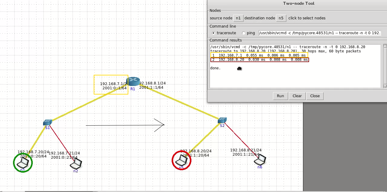
Figure 3.3 Trace routing on neighboring network on Core
3.2 Static Routing
You might need to properly install and configure Quagga to perform this simulation. Please search for tutorials (simulation setup coming soon).
The Internet is said to be the largest WAN in the World, so routing is not something we can ignore. The first form of routing is static routing where we form our path manually. If we have many connections (interface) on our PCs we can set its routing, but by default the only route is via default gateway. On the previous section when we set the default gateway 192.168.7.1 means that to go anywhere else other than the local network we go through 192.168.7.1, or we can say it “default via 192.168.7.1”, or “0.0.0.0/0 via 192.168.7.1”, means “[to go anywhere] [via] [192.168.7.1]”. This is a static route but a default one. Say that we want to connect to another WAN, our router must know the route. Manually we teach the router (static route) on Figure 3.4 and Figure 3.5.
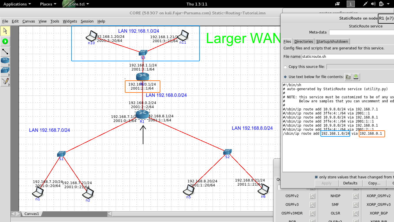
Figure 3.4 Static routing configuration of R1
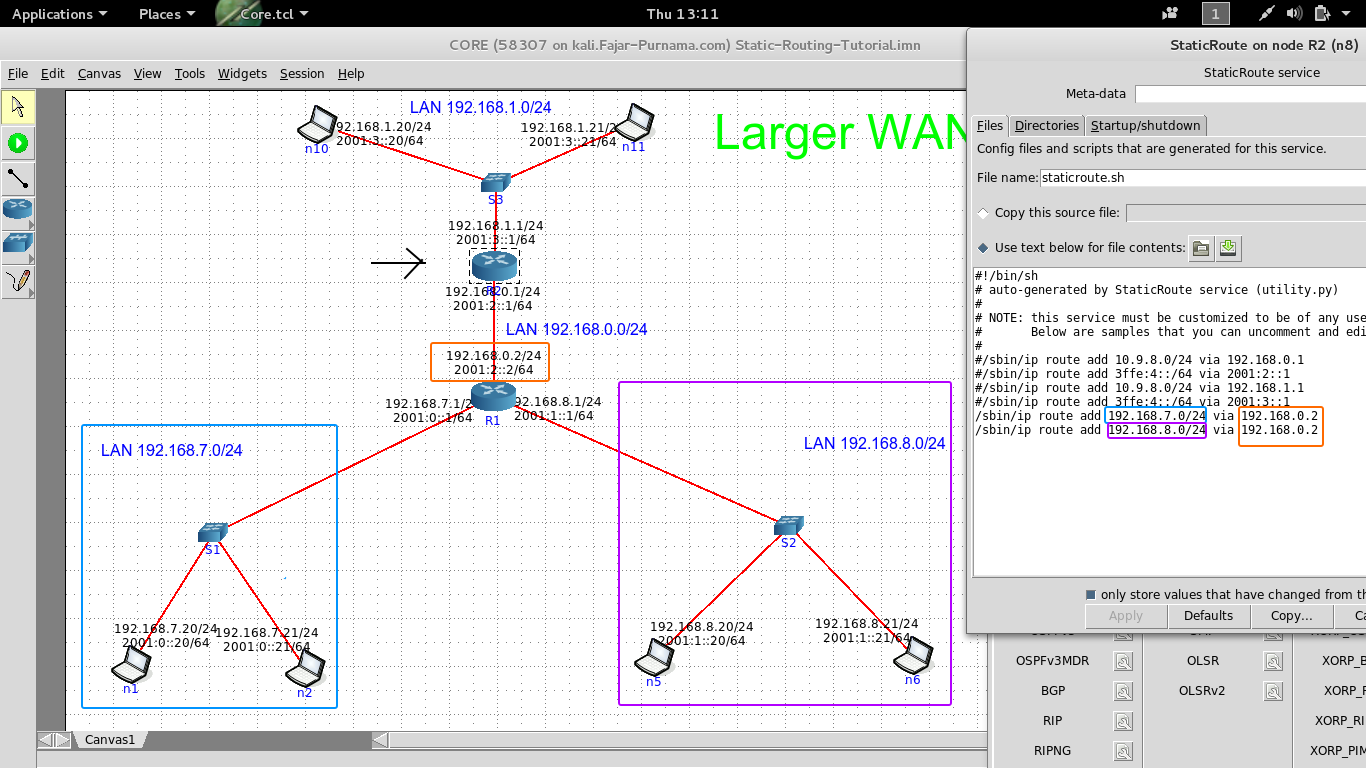
Figure 3.5 Static routing configuration of R2
Connecting R1 and R2 cost us another LAN, in other words connection of R1 and R2 is on LAN 192.168.0.0/24. On Figure 3.4 we want to tell R1 that to go to network 192.168.1.0/24 is through R2. So the command is ip route add 192.168.1.0/24 via 192.168.0.1. n Figure 3.4 we want to tell R2 that to go to network 192.168.7.0/24 and 192.168.8.0/24 is through R2. So 2 commands are involved because we want to define for 2 networks, are ip route add 192.168.7.0/24 via 192.168.0.2 and ip route add 192.168.8.0/24 via 192.168.0.2. Setting only one of the router will not do, since in reality we exchange informations 2 ways. We be able to send a message to other side, but the other side won’t know which way to go to reply the message.
Figure 3.6 GIF Image to activate static route configuration
Figure 3.7 GIF image in trace routing from n1 to n10 and n11 to n6
On Figure 3.6 is a GIF image to set a static route on a router in Core-Network. Finally on Figure 3.7 we check whether the networks are connected using trace route. From n1 to n10 we see that it will go through the first router on gateway 192.168.7.1, then R1 routes it to R2 on gateway 192.168.0.1, which in the end reaches 192.168.1.20. Next we tried from n11 to n6, we see that it will go through the first router on gateway 192.168.1.1, then R2 routes it to R1 on gateway 192.168.0.2, which in the end reaches 192.168.8.21.
3.3 Dynamic Routing
Imagine how much static route you must configure on the scale of a network like The Internet. It’ll still be better if The Internet is a fixed size but in reality is growing larger every second, on top of that configurations may changes every time. Static route is inefficient to implement, instead why not let the router search for the route for themselves? With us only teaching them the method of how to find a route. As the headline of the section, that is dynamic routing which is an automatic/self update routing based on the defined method. We will cover only the way to configure a router information protocol (RIP) dynamic routing (not even the theory behind it), as further is out the syllabus.
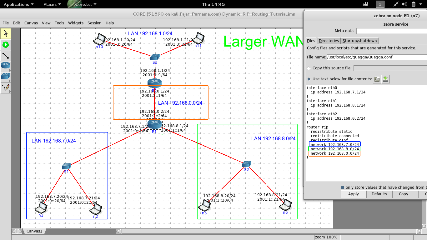
Figure 3.8 RIP configuration on R1
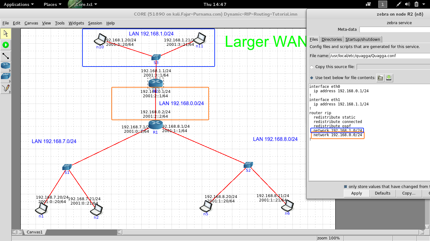
Figure 3.9 RIP configuration on R2
On Figure 3.8 is the RIP configuration of R1 where we add the networks 192.168.7.0/24, 192.168.8.0/24, 192.168.0.0/24, and on Figure 3.9 is the RIP configuration of R2 where we add the networks 192.168.1.0/24, 192.168.0.0/24. Basically we give the information of the networks that is directly connected to router on the RIP configuration. If I’m correct, using RIP will make routers exchange informations with each other of which networks are attached to them. If we want to add another network then we just need to add the network ID, unlike static routing which we must manually define the gateway. Without doubt on that the networks will be connected as on Figure 3.10.
Figure 3.10 GIF image of trace routing
How to open configuration of RIP on Core-Network is on Figure 3.11. Lastly, on this section this might be RIPv1 (I haven’t check) and if it so it will not support classless networks (other than /8, /16, /24), so try the RIPv2 or other dynamic routing protocols.

Figure 3.11 GIF image of configuring RIP on Core-Network
4. Common Features on The Internet
4.1 Dynamic Host Configuration Protocol (DHCP)
The DHCP service lets automatic IP configuration on a client. The client simply ask around the LAN whether a server can give the client an identity. As on the following figures the server may give an IP address, DNS, and default gateway, which depends on the server’s and client’s configuration. Below are figures of example DHCP on Core-Network.
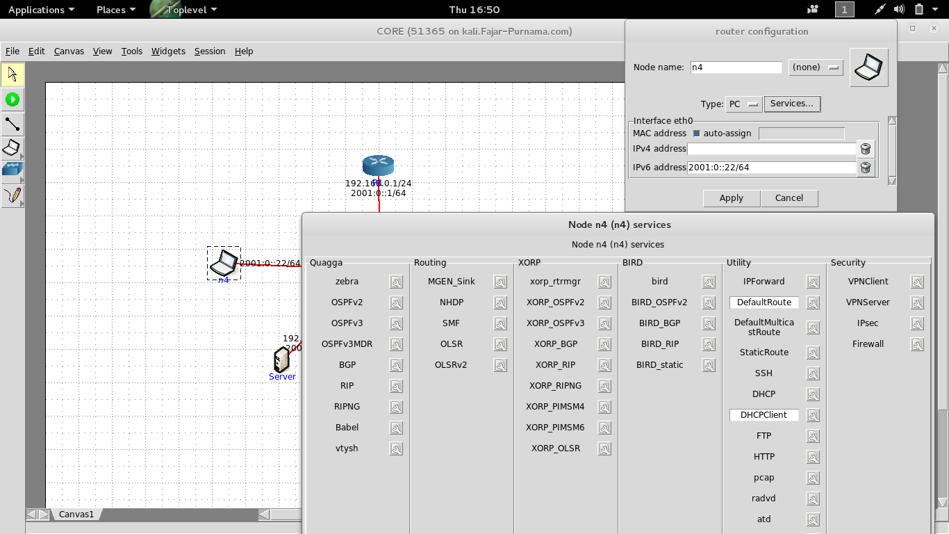
Figure 4.1 Disabling manual IP and activate DHCP
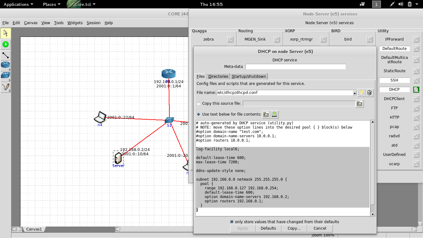
Figure 4.2 DHCP server configuration
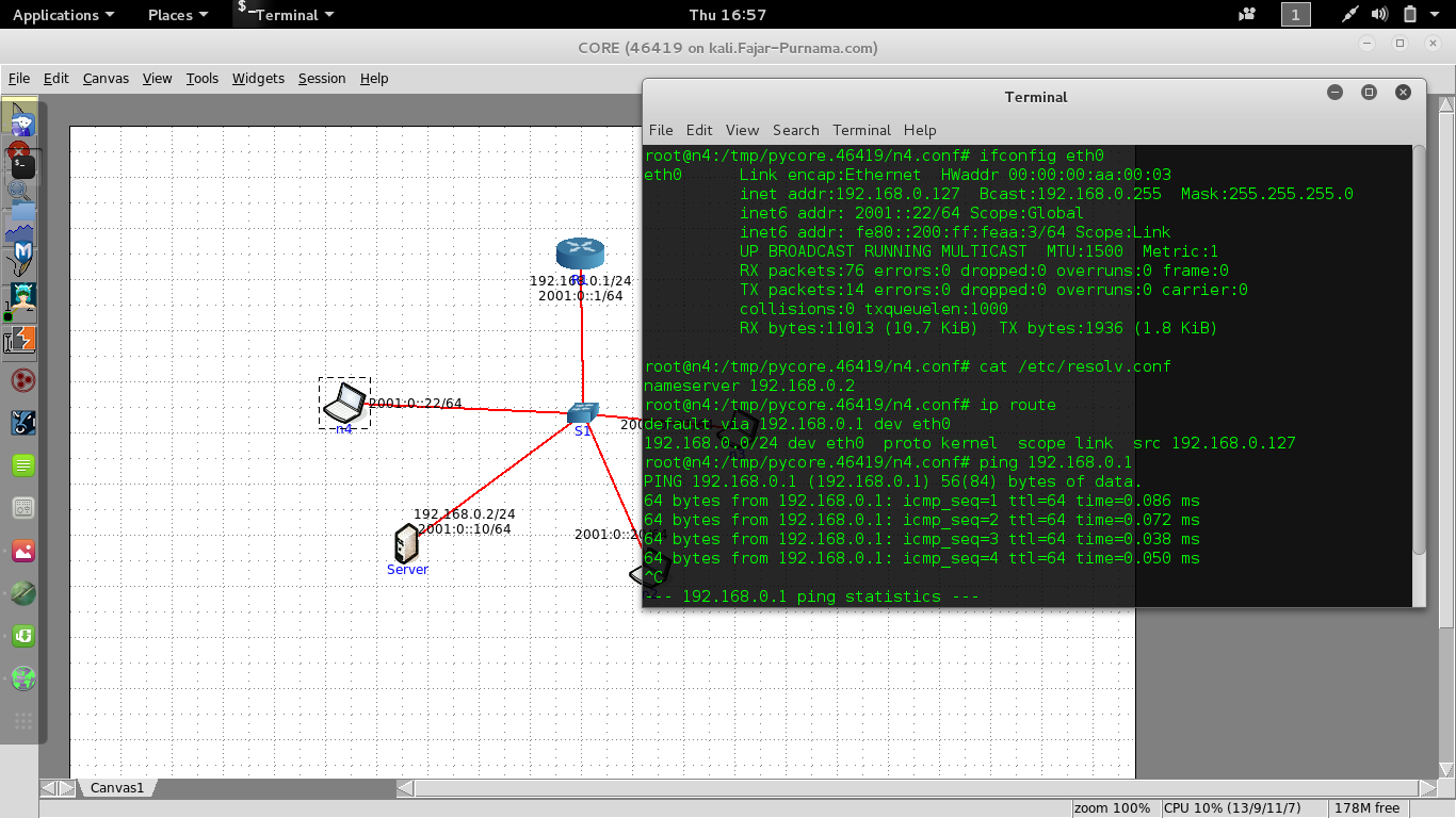
Figure 4.3 Client receives configuration
On Figure 4.1 we activate DHCP and disable manual IP assigning on all clients. On Figure 4.2 we configure the DHCP server with pool of IP address from 192.168.0.127 - 192.168.0.254 and the DNS server is itself, the option router equivalent to the default gateway, and on FIgure 4.3 is the configuration obtained on a client. On the real PC most configuration are DHCP as default as on Figure 4.4.
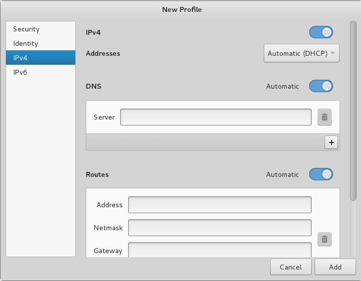
Figure 4.4 Default DHCP setting for Network Manager
4.2 Domain Name Service (DNS)
A DNS server may contain list of domain names of addresses. For example I have a web server on 192.168.100.253, without DNS I have to type http://192.168.100.253 to access the web page through my browser. For me it’s too hard to remember, instead I’d to give my server a domain name or register a domain name to my server. Say I would like to give www.myfakegoogle.com to 192.168.100.253. Whenever I write www.myfakegoogle.com will correspond to 192.168.100.253. DNS translated an IP address to domain name and vice versa.
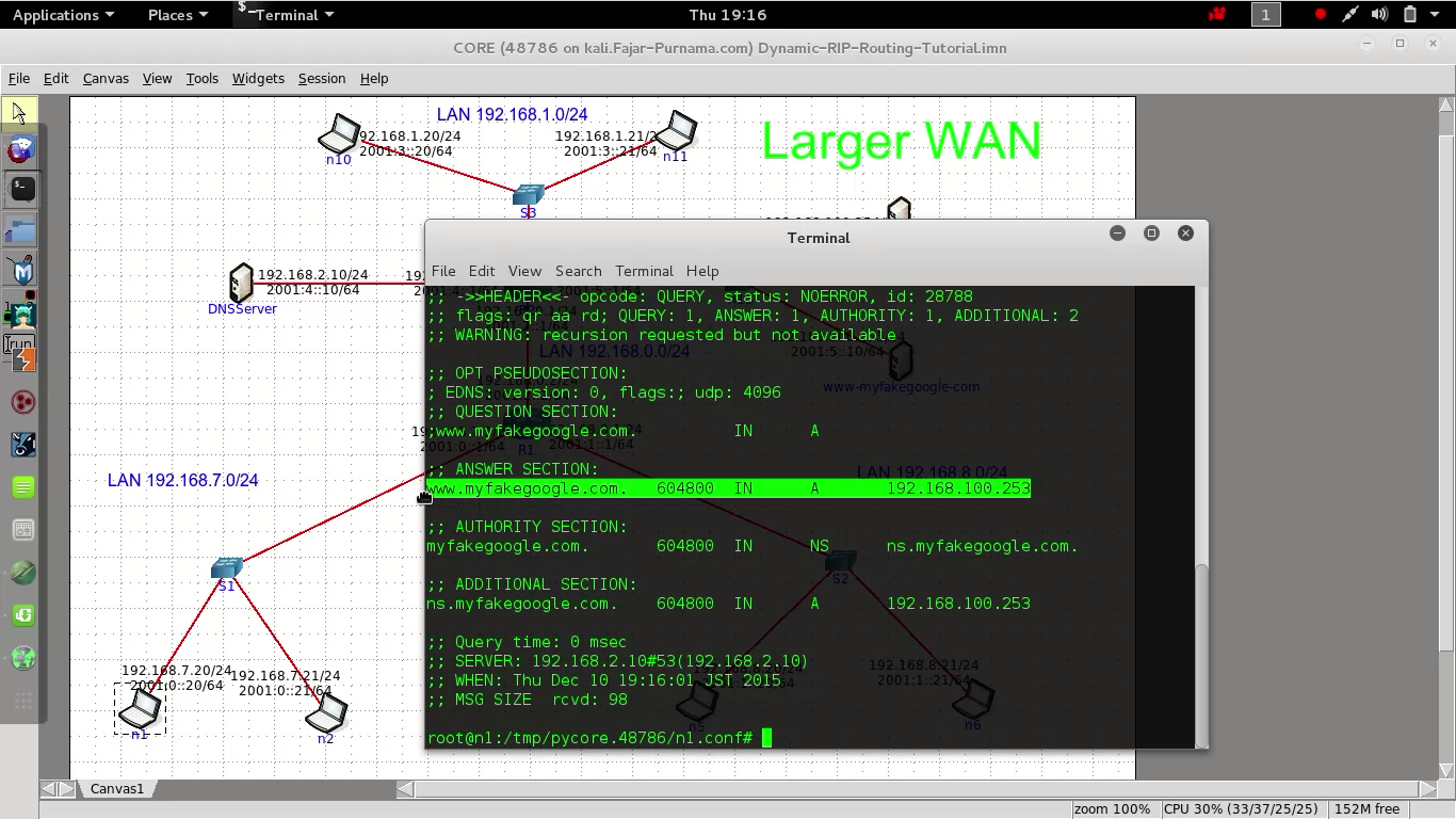
Figure 4.5 Dig the domain name
I tried to simulate DNS on Core-Network but cannot find the feature. So I have to manually define a DNS server on the simulator by installing and connecting a real DNS server on my machine. I used bind9, I’m not familiar with the configuration, so I skip the explanation here and show that I have configured 192.168.100.253 as www.myfakegoogle.com on Figure 4.5.
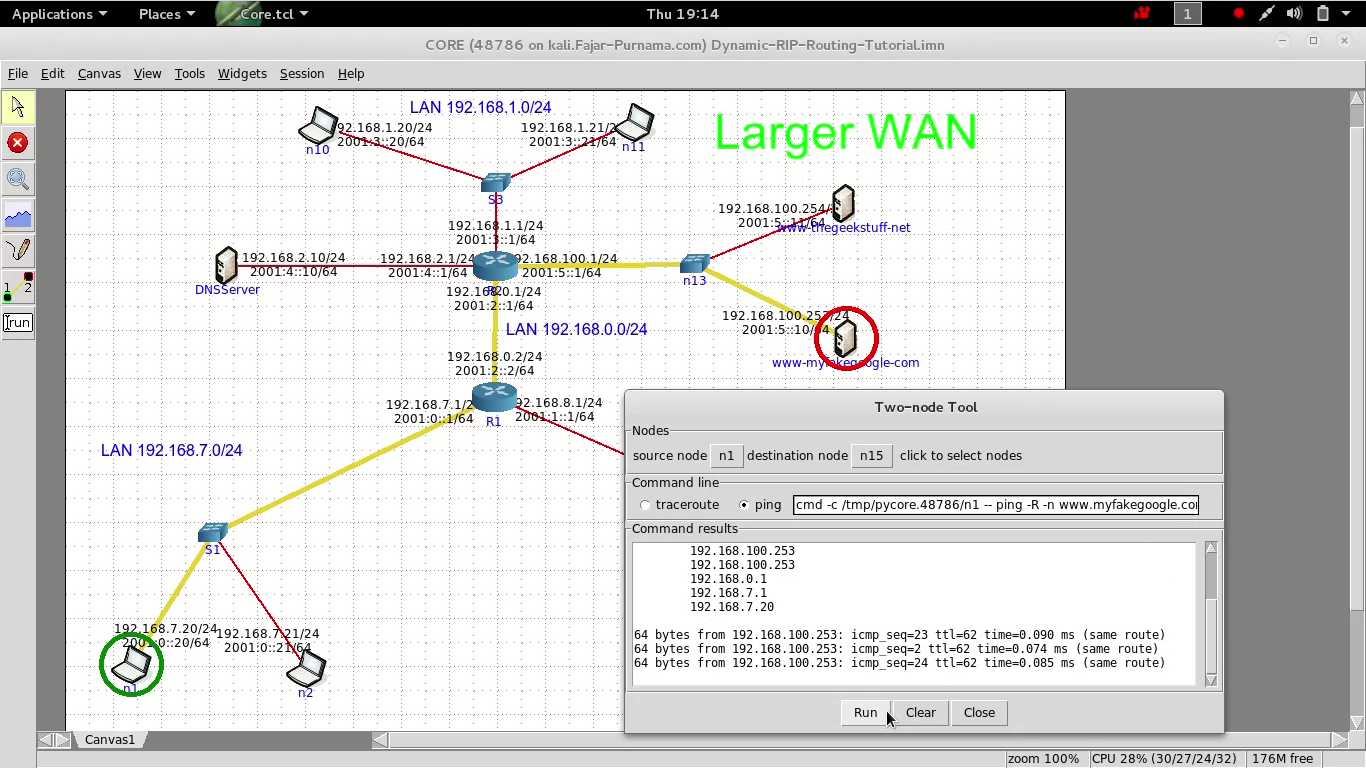
Figure 4.6 Try DNS on Core-Network
I made a DNS server on the Core-Network using the userdefined feature (connecting Bind9 to it) and successfully ping using the domain name on Figure 4.6. If you look closely it’s like a picture of a mini version of The Internet considering a PC wants to connect to www.google.com (this is my mini version of The Internet). If we install a web browser on www.myfakegoogle.com then we access it on the browser. To check a domain name on real network use dig or nslookup.
4.3 Web Server
A web page uses Hyper Text Transfer Protocol to display the page on the browser. To be honest it’s very wide and the only thing we can show you here is this example web page use to develop this content. Installing a web server on a machine allows information exchange using the web browser. A free web browser is Apache2, for beginners may use bundles like XAMPP or LAMPP. Lastly on section 4, if we combine everything up till now, we can create a tiny version of The Internet.

Figure 4.7 Apache2
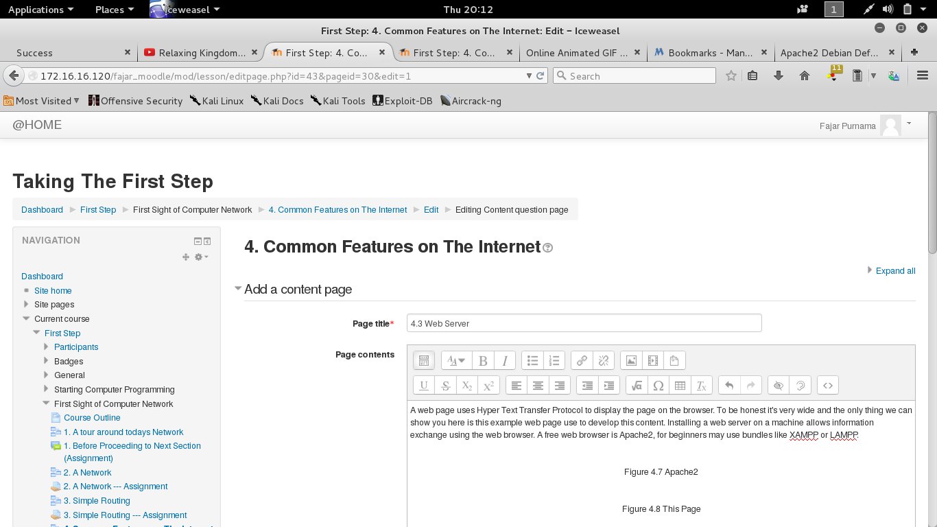
Figure 4.8 Elearning Moodle
Mirrors
- https://www.publish0x.com/0fajarpurnama0/simple-introduction-to-computer-network-and-the-internet-xwpmdk?a=4oeEw0Yb0B&tid=github
- https://0fajarpurnama0.github.io/cryptocurrency/2020/03/24/simple-introduction-to-computer-network
- https://steemit.com/computer/@fajar.purnama/simple-introduction-to-computer-network-and-the-internet?r=fajar.purnama
- https://hicc.cs.kumamoto-u.ac.jp/~fajar/cryptocurrency/simple-introduction-to-computer-network.html
- https://medium.com/@0fajarpurnama0/simple-introduction-to-computer-network-and-the-internet-f97001834276
- https://0darkking0.blogspot.com/2020/03/simple-introduction-to-computer-network-and-the-internet.html
- https://0fajarpurnama0.wixsite.com/0fajarpurnama0/post/simple-introduction-to-computer-network-and-the-internet
- http://www.teiii.cn/simple-introduction-to-computer-network-and-the-internet
- https://0fajarpurnama0.cloudaccess.host/index.php/uncategorised/18-simple-introduction-to-computer-network-and-the-internet
- http://0fajarpurnama0.weebly.com/blog/simple-introduction-to-computer-network-and-the-internet
- https://0fajarpurnama0.tumblr.com/post/613409279480856576/simple-introduction-to-computer-network-and-the