My Summary in Advanced Telecommunication Engineering Course
Get 1000000 0FP0EXP Token to remove widget entirely!
Get 500000 0FP0EXP Token to remove my NFTS advertisements!
My Impression on This Class
My undergraduate is in electrical engineering in the field of telecommunications but I knew only a little of telecommunications and excels at programming and computer network. Back then I was unfortunate in taking a short electromagnetic wave course that the course was until before maxwell equation which is why I did not know about maxwell equation. In the end I’m very weak on that field and finds it hard to study antennas. Thanks to this masters course I was able to learn more of my field and cover some of my weaknesses. If I could give suggestion of this course, I would suggest the use of computer simulations such as Octave to demonstrate electromagnetic waves and polarization, Splat for RF propagation, or nec2c for antenna design simulation which will make the course more interesting. These are opensource softwares. This assignment except the images has never been published anywhere and I, as the author and copyright holder, license this assignment customized CC-BY-SA where anyone can share, copy, republish, and sell on condition to state my name as the author and notify that the original and open version available here.
What is the difference between the LOS and NLOS environment?
- LOS stands for line of sight where in propagation the transmitter and receiver can physically see each other, while NLOS stands for non line of sight, the opposite of LOS where the transmitter and receiver cannot physically see each other.
- In a LOS environment we mainly examine the link budget. The link budget in general consist of three factors which are (1) the power generated at the transmitter, (2) free space loss, (3) the power can be receive on the receiver. On the transmitter and receiver side there is the electrical power generated, cable loss of the transmission line, and the gain of the antenna which is mainly affected by the directivity. The 2 main factors that affects the free space loss are the frequency of the signal and the distance between the transmitter and the receiver.
- However there are more factors to be considered in a NLOS environment, eventhough it also exist on LOS environment but not as strong. On Figure 1 shows a comparison illustration between LOS and NLOS where basically daisy chain, penetration, reflection, and diffraction usually occurs on NLOS. On the penetration side not all the radio waves can pass through resulting a loss cause by an interfering object, some waves are reflected depending on the object and the characteristic of the radiation, and sharp edges on objects cause waves to be diffracted. This leads to multipath where the same wave got scattered and arrives on the same receivers as duplicates. Duplicates cause garbages but a wave arrived at same time can either have positive or negative affect. If the signals are on the same phase it powers each other, but if it’s on opposite phase it cancels each other which is the phenomenon of fading. Depending on the difference of each other’s amplitude (strength) the fading can be tolerateable or severe. In telecommunication many types of fadings were defined such as Nakagami fading, log-normal shadow fading, rayleigh fading, rician fading, and weibull fading. The are also several techniques currently used to mitigate fadings such as diversity (using multi-transmitter-receiver and choose which one is the best), multiple input multiple output (MIMO), orthogonal frequency division multiplexing (OFDM), rake receivers, and space time codes.
- On the real environment calculating all the factors are very tough, but instead we can use models such as Okumura-Hata model and Walfisch-Ikegami model.
- Reference: http://www.ie.itcr.ac.cr/acotoc/Maestria_en_Computacion/Sistemas_de_Comunicacion_II/Material/Biblio5.pdf
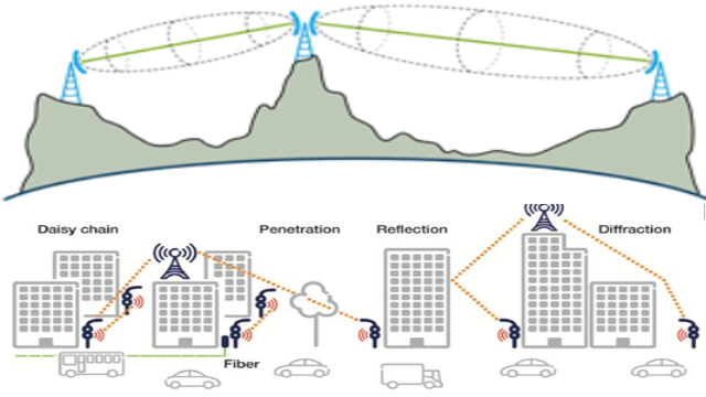
Figure 1. LOS and NLOS illustration. (https://commons.wikimedia.org/wiki/File:Line_of_sight_mw_transmission.svg, http://www.ericsson.com/res/site_US/docs/2015/connections/NLOS-Study-Jan2015.pdf)
What is the merit of using circular polarization in wireless communication and describe examples of applications of circular polarization?
- The electromagnetic consist of electric field and magnetic field. Based on Maxwell-Faraday equation the voltage accumulated around a closed circuit is proportional to the time rate of change of the magnetic flux it encloses (∇×E=(-∂B)/∂t), and Ampere’s circuital law electric currents and changes in electric fields are proportional to the magnetic field circulating about the area they pierce (∇×B=μ_o (J+ε_o ∂E/∂t)). The electric field determines the orientation of the radio wave or polarization. The polarization can either be linear polarization (vertical or horizontal) or circular polarization as shown on Figure 2.
- On wireless communication, antenna is one of the heart of the system. Antenna converts electric current to electromagnetic wave and radiates it into space to transmit information, and vice versa receives and converts electromagnetic wave to electric current to receive information. An antenna can either be vertically, horizontally, circularly, or eliptically polarized. For the transmitter and receiver side both antennas have to be the same vertically or horizontally polarized or a big loss can be expected (it can be imagined in Figure 2). For this the antenna have to be in fixed position (if change the polarization changes), in other words static.
- On the other hand circular polarized antenna allows dynamic or changing position, because no matter how the position changes, the polarization will remain circular. This is the main benefit for circular polarization. An implementation for this is the satellite, since the geometry of the receiving antenna on Earth is not fix (the Earth is round and constantly rotating), using circular polarization keeps a constant signal strength eventhough the position constantly changing everytime. Another merit is not only it could work on the same both polarization, but communication with antenna with either vertical or horizontal polarization is possible with the loss around 3dB. Also it can greatly decrease the fading phenomenon, usually on linear polarization there are chances the a signal can meet with other signals that had the opposite phase which in the end cancels each other. Since the polarization is circular this kind of phenomenon should not happen.
- Another application that is most likely using circular polarization is our portable device like laptops, handphones, and gadgets. I can’t really say today it’s the implementation because it uses something more, it uses more than one type of polarization.
- Reference: http://www.astronwireless.com/topic-archives-antennas-polarization.asp
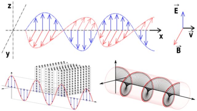
Figure 2. Electromagnetic wave, linear polarization, and circular polarization. https://en.wikipedia.org/wiki/File:Onde_electromagnetique.svg, https://commons.wikimedia.org/wiki/File:Linear_Polarization_Linearly_Polarized_Light_plane_wave.svg, https://en.wikipedia.org/wiki/File:Circular.Polarization.Circularly.Polarized.Light_Without.Components_Left.Handed.svg)
There are many kinds of antennas, why many different kinds of antennas should exist?
- Many factors determines the design of an antenna, but only a few will be listed here. For section 2 is already mentioned that the type of polarization desired will affect the design of an antenna. Monopoles, and dipoles antenna are linearly polarized, while coverleaf, and helix antenna have circular polarization.
- Other than polarization the gain of the antenna is another factor. A Yagi-Uda antenna have a high gain and widely use in ultra high frequency for T because of the adjustable directivity. A corner reflector antenna have a high directivity and parabolic reflector today provides the highest gain and directivity which is used in a very long telecommunication between outer space satellite and the earth. The radiation pattern is very sharp, unlike Yagi-Uda antenna that we can easily adjust to aim at a TV station, a parabolic reflector must be aim very accurately.
- The next factor is the resonance and bandwidth factor. The term impedance is very crucial to antenna that if the impedance doesn’t match, the power source cannot deliver power to the antenna for radiation and the other way around the antenna can deliver received power to the source. A short dipole antenna seems quite difficult for impedance matching because the parameter changes wildly as frequency changes. A folded dipole on the other hand is different and tends to be resonance (able to deliver max power). The bandwidth factor means on how many frequency an antenna can operate. A Yagi-Uda antenna had low bandwidth, but a log periodic and spiral antenna have high bandwidth.
- The antennas mentioned above usually stand alone (placed on a rooftop for example) while antennas that can be embedded into a device is needed for our portable device like laptops, and handphones. The design have to be more flexible and offers wide specifications including the ones mentioned above. Example of these types antennas are inverted F, slotted, and microstrip antennas.
- Figure 3 shows some pictures of antennas. Reference: http://www.antenna-theory.com
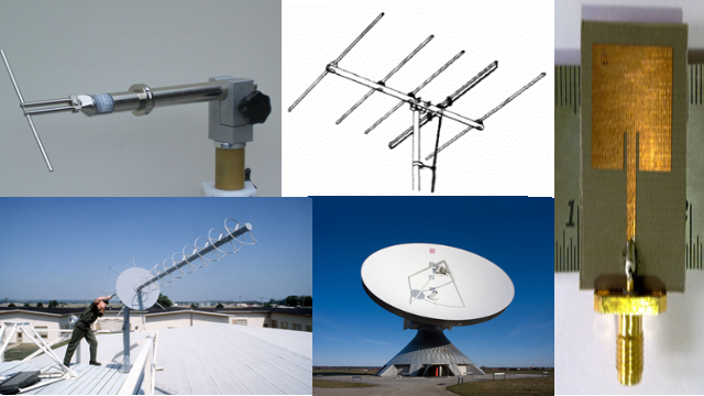
Figure 3. Half-Wave Dipole, Yagi-Uda, Helical, Parabolic, and Microstrip Antenna. ( [https://en.wikipedia.org/wiki/File:Half_%E2%80%93Wave_Dipole.jpg](https://en.wikipedia.org/wiki/File:Half%E2%80%93_Wave_Dipole.jpg), https://en.wikipedia.org/wiki/File:Yagi_TV_antenna_1954.png, https://en.wikipedia.org/wiki/File:Hammer_Ace_SATCOM_Antenna.jpg, https://en.wikipedia.org/wiki/File:Erdfunkstelle_Raisting_2.jpg, http://file.scirp.org/Html/4-9801338%5Ce5febaf1-266f-41ac-aa10-81c43316ec89.jpg)
Mirrors
- https://www.publish0x.com/fajar-purnama-academics/my-summary-in-advanced-telecommunication-engineering-course-xvwyvlz?a=4oeEw0Yb0B&tid=github
- https://0darkking0.blogspot.com/2021/01/my-summary-in-advanced.html
- https://0fajarpurnama0.medium.com/my-summary-in-advanced-telecommunication-engineering-course-5c70e239eaa7
- https://0fajarpurnama0.github.io/masters/2020/09/01/summary-advanced-telecommunication-engineering-course
- https://hicc.cs.kumamoto-u.ac.jp/~fajar/masters/summary-advanced-telecommunication-engineering-course
- https://steemit.com/engineering/@fajar.purnama/my-summary-in-advanced-telecommunication-engineering-course?r=fajar.purnama
- https://stemgeeks.net/engineering/@fajar.purnama/my-summary-in-advanced-telecommunication-engineering-course?ref=fajar.purnama
- https://blurt.buzz/blurtech/@fajar.purnama/my-summary-in-advanced-telecommunication-engineering-course?referral=fajar.purnama
- https://0fajarpurnama0.wixsite.com/0fajarpurnama0/post/my-summary-in-advanced-telecommunication-engineering-course
- http://0fajarpurnama0.weebly.com/blog/my-summary-in-advanced-telecommunication-engineering-course
- https://0fajarpurnama0.cloudaccess.host/index.php/9-fajar-purnama-academics/177-my-summary-in-advanced-telecommunication-engineering-course
- https://read.cash/@FajarPurnama/my-summary-in-advanced-telecommunication-engineering-course-b0756f27
- https://www.uptrennd.com/post-detail/my-summary-in-advanced-telecommunication-engineering-course~ODQ5MDc3