Assignment About Flow Control and Selective Repeat ARQ
Note
This is my undergraduate assignment that I translated to English myself in the Data Communication course where my assignment is to write an essay on flow control, error detection and control, and selective repeat ARQ. Apart from me, this group consists of I Gede Ariana, I Made Dwi Angga Pratama, I Putu Arie Pratama, Yulianti Murprayana, I Wayan Alit Wigunawan, I Gusti Made Widiarsana, I Nym Apriana Arta Putra, Muhammad Audy Bazly, I Kadek Agus Riki Gunawan, Muhamad Nordiansyah. This task has never been published anywhere and we as the authors and the copyright holders license this task customized CC-BY-SA where anyone can share, copy, republish, and sell on condition to state our name as the author and notify that the original and open version available here.
Chapter 1 Introduction
1.1 Background
The development of computer technology is increasing very rapidly, this can be seen in the 80s that computer networks are still a puzzle that academics want to answer, and in 1988 computer networks began to be used in universities, companies, and now. Entering this millennium era, especially WWW (World Wide Web) has become the daily reality of millions of people on this earth.
In addition, network hardware and software have really changed, at the beginning of its development almost all networks were built from coaxial cables, now many of them are built from fiber optics (fiber optics) or wireless communication.
With the development of computer and communication technology, a single computer model that serves all the computing tasks of an organization has now been replaced by a collection of computers that are separate but interconnected in carrying out their duties, such a system is called a computer network.
Two computers are said to be interconnected if they can exchange information. The form of connection does not have to go through copper wire alone but can use optical fiber, microwave, or communication satellites.
In a data communication, data packets are sent through a certain medium, there will always be a difference between the sent signal and the received signal. This difference can result in an error or error in the data packet sent so that the data cannot be read properly by the recipient. To avoid errors or errors in the data packets sent, error detection (error checking), error correction (error correction) and error control (error control) are required. In error control, there are three methods that are often used in data communication, namely stop and wait requests, go back N requests, and selective requests. Error control includes the following mechanisms: ACK/NAK, timeout, and sequence number. In error control, the following processes occur: error detection, acknowledgment, transmission after timeout, and negative acknowledgment.
1.2 Problem
The formulations of the problems raised in this paper are as follows:
- What is flow control?
- What is error detection and correction and how to minimize it?
- What is Selective Repeat ARQ?
1.3 Objective
The objectives of this paper are as follows:
- Able to define the meaning of flow control.
- Able to provide a definition of the meaning of error detection and correction, and how to minimize errors that occur.
- Able to explain the definition of Selective Repeat ARQ.
1.4 Scope of Material
In this assignment, the scope discussed by the author is only limited to the issues discussed, which is limited to Selective Repeat ARQ in a data communication network, and also to provide an overview to readers about the process of controlling errors in data communication.
Chapter 2 Discussion
The purpose of error control is to deliver error-free frames in the correct order to the network layer. The technique commonly used for error control is based on two functions, namely:
- Error detection, usually using the CRC (Cyclic Redundancy Check) technique.
- Automatic Repeat Request (ARQ), when an error is detected the sender asks to resend the frame where an error occurs.
Meanwhile, error control is divided into three, namely:
- Manual Error Control. For example, if we make a mistake in typing we correct it by deleting the wrong character, for example with the delete or backspace key.
- Echo Checking. The same procedure is used when a terminal is connected to a remote computer, say using an analog PSTN and a modem. In addition, each character entered is displayed directly on the display terminal, the first time it is transmitted to the remote computer. The remote computer then reads and stores the characters and retransmits them to the terminal that displays them. If it is different from what has been entered the user can restart transmission for erasing incorrect characters.
- Automatic Repeat Request. Consists of idle requests and continuous requests. We will discuss more about continuous requests, especially selective repeat.
2.1 Flow Control
Flow control is a technique for ensuring that a sending station does not flood the receiving station with data. The receiving station will typically provide a data buffer of a specified length. When the data is received, it has to do some work before it can clear the buffer and prepare for the next data reception.
A simple form of flow control known as stop and wait, it works as follows. The recipient indicates that it is ready to receive data by sending a poll or responding with select. The sender then sends the data.
This flow control is regulated/managed by Data Link Control (DLC) or commonly referred to as Line Protocol so that the sending and receiving of thousands of messages can occur in the shortest possible time. The DLC must move data in efficient traffic. Communication lines should be used as level as possible, so that no station is idle while the other stations are saturated with excess traffic. So flow control is a very critical part of a network. The following shows the Time Flow Control Diagram when communication occurs in conditions without errors and errors. Flow control mechanisms that are commonly used are Stop and Wait and Sliding window.
Figure 2.1 Time flow control diagram during transmission without errors (a) and when packet loss and error occur (b)
2.2 Error Detection and Correction
As a result, the physical processes that cause errors in some media (for example, radio) tend to occur in bursts rather than one by one. Error bursting like that has both the advantage and the disadvantage of isolated single-bit errors. On the plus side, computer data is always sent in blocks of bits. Assume the block size is 1000 bits, and the error rate is 0.001 per bit. If the errors are independent, then most blocks will contain errors. If an error occurs with 100 bursts, then only one or two blocks in 100 blocks will be affected, on average. The disadvantage of burst errors is that they are more difficult to detect and correct than isolated errors.
2.2.1 Error Correction Codes
The network designers have devised two basic strategies regarding errors. The first way is to involve sufficient redundant information together with each block of data transmitted to allow the recipient to draw conclusions about what the transmitted character should be. Another way is to involve only enough redundancy to draw the conclusion that an error has occurred, and to allow it to request retransmission. The first strategy uses error-correcting codes, while the second strategy uses error-detecting codes.
In order to understand error handling, it is necessary to take a close look at what errors are. Typically, a frame consists of m bits of data (i.e. messages) and redundant r, or check bits. Take the total length of n (that is, n = m + r). An n-bit unit of data and a checkbit is often associated with an n-bit codeword.
Two codewords are specified: 10001001 and 10110001. Here we can determine how many different corresponding bits are. In this case, there are 3 different bits. To determine it, simply perform an EXCLUSIVE OR operation on both codewords, and count the number of bits 1 in the result of the operation. The number of bit positions where the two codewords differ is called the Hamming distance (Hamming, 1950). The thing to note is that if two codewords are separated by a Hamming distance d, it will take a single bit error d to convert from one to the other.
In most data transmission applications, all 2m of data messages are legal data. However, due to the way the check bit is calculated, not all 2n are used. If an algorithm is specified for calculating the check bits, it is possible to generate a complete list of legal codewords. From this list two codewords with the minimum Hamming distance can be found. This distance is the Hamming distance for the complete code.
The error detection and error correction properties of a code depend on the Hamming distance. To detect d errors, you need a code with a distance of d + 1 because with such a code it is impossible that a single bit error d can change one valid codeword to another valid codeword. When the receiver sees an invalid codeword, it can say that an error has occurred during transmission. Likewise, to fix error d, you need a code that is 2d + 1 apart because it says legal codewords can be separated even with a change to d, the original codeword will be closer than other codewords, so error fixes can be determined uniquely.
As a simple example of error detection code, take a code where a single parity bit is appended to the data. The parity bit is chosen so that the number of 1 bits in the codeword is even (or odd). For example, if 10110101 is sent in even parity by adding a bit at the end, the data becomes 101101011, whereas with even parity 10110001 becomes 101100010. A code with a single parity bit has a distance of 2, because any single bit error results in a codeword with parity. wrong. This method can be used to detect a single error.
As a simple example of error correction code, take a code that has only four valid codewords: 0000000000, 0000011111, 1111100000 and 1111111111. This code has a space of 5, which means that it can fix multiple errors. When the codeword 0000011111 arrives, the recipient will know that the original data should be 0000011111. However, if the triple error changes 0000000000 to 0000000111, the error cannot be corrected.
Imagine that we are going to design code with m message bits and r check bits that will allow all single errors to be fixed. Each of the 2m legal messages requires an n + 1 bit pattern. Since the total number of bit patterns is 2 n, we must have (n + 1) 2 m ≤ 2 n. Using n = m + r, this requirement becomes (m + r + 1) ≤ 2 r. When m is specified, it places a lower limit on the number of check bits required to correct a single error.
In fact, this theoretical lower limit can be obtained using the Hamming method. The codeword bits are numbered consecutively, starting with bit 1 on the far left. Bits that are powers of 2 (1,2,4,8,16 and so on) are check bits. The rest (3,5,6,7,9 and so on) are inserted with m bits of data. Each check bit forces the parity of a portion of the bit set, including itself, to be even (or odd). A bit can be included in multiple parity computations. To find the check bit to which the data bit at position k contributes, rewrite k as a sum to the powers of 2.For example, 11 = 1 + 2 + 8 and 29 = 1 + 4 + 8 + 16. A bit is checked by the check bit that occurs in its expansion. (for example, bit 11 is checked by bits 1, 2 and 8).
When a codeword arrives, the receiver initializes the counter to zero. Then the codeword checks each check bit, k (k = 1, 2, 4, 8, …) to see if it has the correct parity. If not, the codeword will add k to the counter. If the counter equals zero after all the check bits have been tested (that is, if all the check bits are true), the codeword will be accepted as valid. If the counter is not zero, the message contains an invalid number of bits. For example, if the check bits 1, 2, and 8 have an error, then the inversion bit is 11, because that’s the only one checked by bits 1, 2, and 8. Figure 2.2 illustrates some of the 7-bit encoded ASCII characters as an 11 bit codeword using Hamming code. Note that the data is in the bit positions 3, 5, 6, 7, 9, 10, 11.
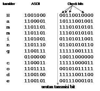
Figure 2.2 Using Hamming code to correct burst errors
Hamming code can only fix a single error. However, there is a trick that can be used to allow Hamming’s code to fix popping errors. A consecutive k number of codewords are arranged as a matrix, one codeword per row. Typically, data will be transmitted one codeword line at a time, from left to right. To correct popped errors, data must be transmitted one column at a time, starting with the leftmost column. When all the k bits have been sent, the second column begins sending, and so on. When the frame arrives at the receiver, the matrix is reconstructed, one column per unit time. If an error burst occurs, at most 1 bit per k codeword will be affected. However Hamming code can fix one error per codeword, so the entire block can be fixed. This method uses the kr check bit to make km of data bits immune to single error bursts of length k or less.
2.3 Selective Repeat ARQ
Selective Repeat or also known as Selective-reject. With selective reject automatic repeat request (ARQ), the frames that will be sent are only those frames that receive a negative reply, in this case called SREJ or frames whose time has expired.
The method of selective-reject ARQ in correcting errors is by at first the transmitter part sends a continuous stream of data from a continuous frame, on the receiving side the data is stored and a cyclic redundancy check (CRC) process is carried out. But this CRC process takes place on a continuous stream of data from the received frame. When an error frame is encountered, the receiver sends the information to the sender via the “return channel”. The sending part then takes the frame from the data storage area and puts it in the transmission queue. There are several important points for frame readers, the first is that there must be a way to identify the frame. The second is that there has to be a good way to know if the frame is getting a positive reply or a negative one.
Both of these important points can be solved by using sequential numbers sent and received. The sequential number that is sent is at the sender, as well as the sequential number that is received at the receiver. Received sequential numbers that are sent back on the sender’s side are the sequential numbers sent by the sender side and get a positive reply from the receiving side. When the receiving side detects an error in the frame, the receiving side will send a sequential number that is sent along with the frame that is considered an error. Of course, in the end the receiving side has to rearrange the frames in the same order as the sending side before the data is passed on to the end user.
Selective-reject ARQ is more efficient against Go-Back-N as it reduces the number of retransmissions. However, selective-reject requires a larger data storage capacity for both the sender and receiver side to store the frame until the damaged frame is retransmitted. In addition, on the receiver side there must also be software that can send frames out of sequence so that data can arrive in sequence to the end user. Selective repeat can be implemented in two ways:
- S indicates that the frame was received correctly and P determines from the received ACK sequence that a frame has been lost (implicit retransmission)
- S returns a special negative statement due to missing frames from the sequence (explicit request)
From these two events, the frame event is received out of sequence, S holds this frame on the receiving channel until the next incoming frame sequence is received. In the case of implicit retransmission, assuming all ACK frames are received correctly, this can be explained as follows (Figure 2.3):
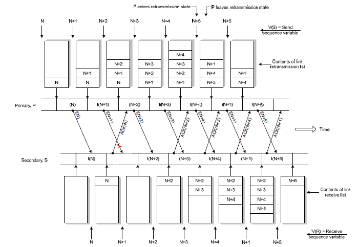
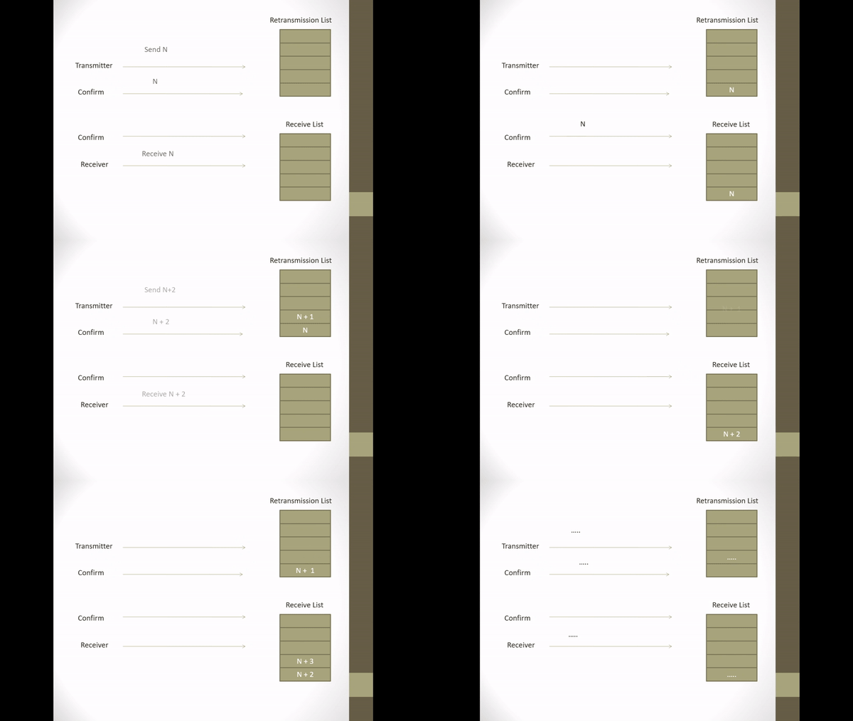
Figure 2.3 Implicit Retransmission corrupted I-frame
- It is assumed that the I-frame N + 1 is damaged (missing)
- S returns an ACK frame for each correctly received I-frame.
- S returns ACK frames for I-frames N, N + 2, N + 3.
- On ACK reception for I-frame N + 2, P notices that N + 1 frames were not received.
- In order to know that more than 1 I-frame is corrupted, P enters the retransmission state of the missing (not received) frames.
- In this condition, transmission of new frames is delayed until frames that were not received are retransmitted.
- P removes I-frames N + 2 from the retransmission list and resends I-frames N + 1 before transmitting N + 5 frames.
- In receiving I-frame N + 1, the contents of the queued frame on the receive list link are sent by S to LS_user in the correct order.
Whereas implicit retransmission assuming that all I-frames are received correctly except ACK frame N can be explained as follows.
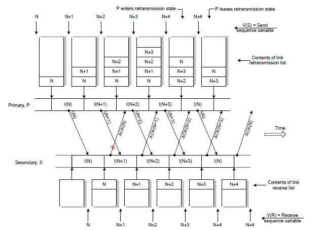
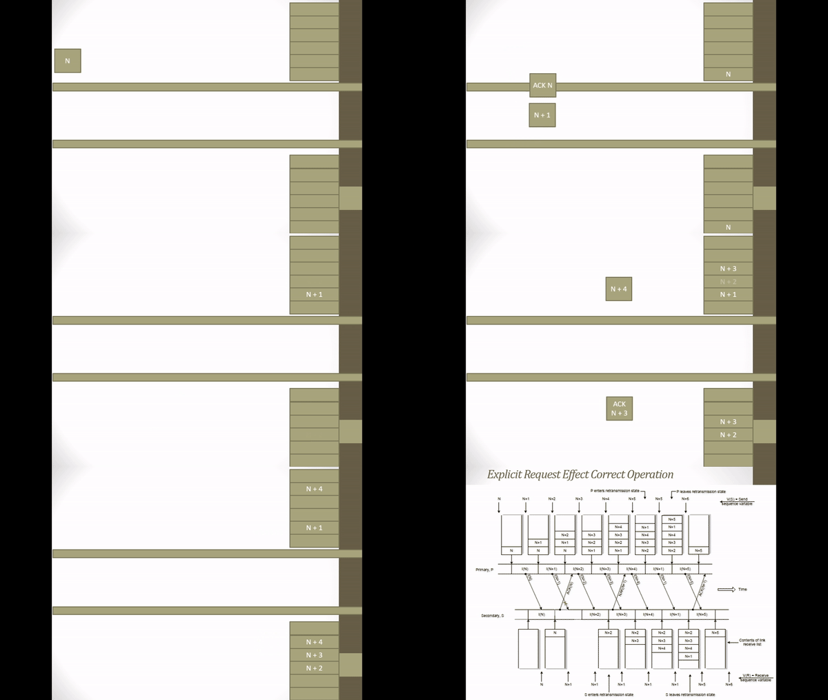
Figure 2.4 Implicit Retransmission corrupted ACK-frame
- On receiving ACK frame N + 1 P knows that I-frame N is still waiting for the statement to be received correctly. So P transmits I-frame N.
- On reception the I-frame N which is transmitted S determines from the sequence variable that the frame has been received correctly and is therefore a duplicate.
- S discards the frame but returns the ACK of the frame to replace it to ensure P removes the frame from the retransmission list.
The above operation relies on receiving the ACK frame associated with subsequent frames to initiate retransmission of the previous damaged frame. Another attempt is to use explicit negative acknowledgment frames to request retransmit the error frames. The negative acknowledgment is known as selective reject. On explicit requests, the assumption that acknowledgments are lost on the way can be explained as follows (see Figure 2.5 below).
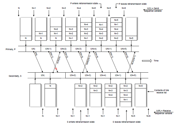
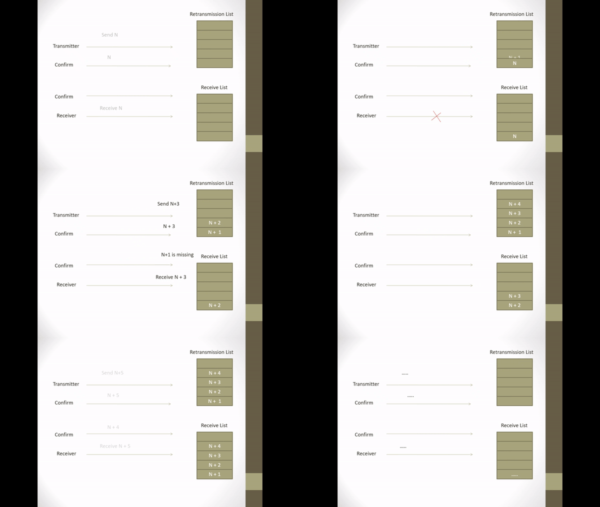
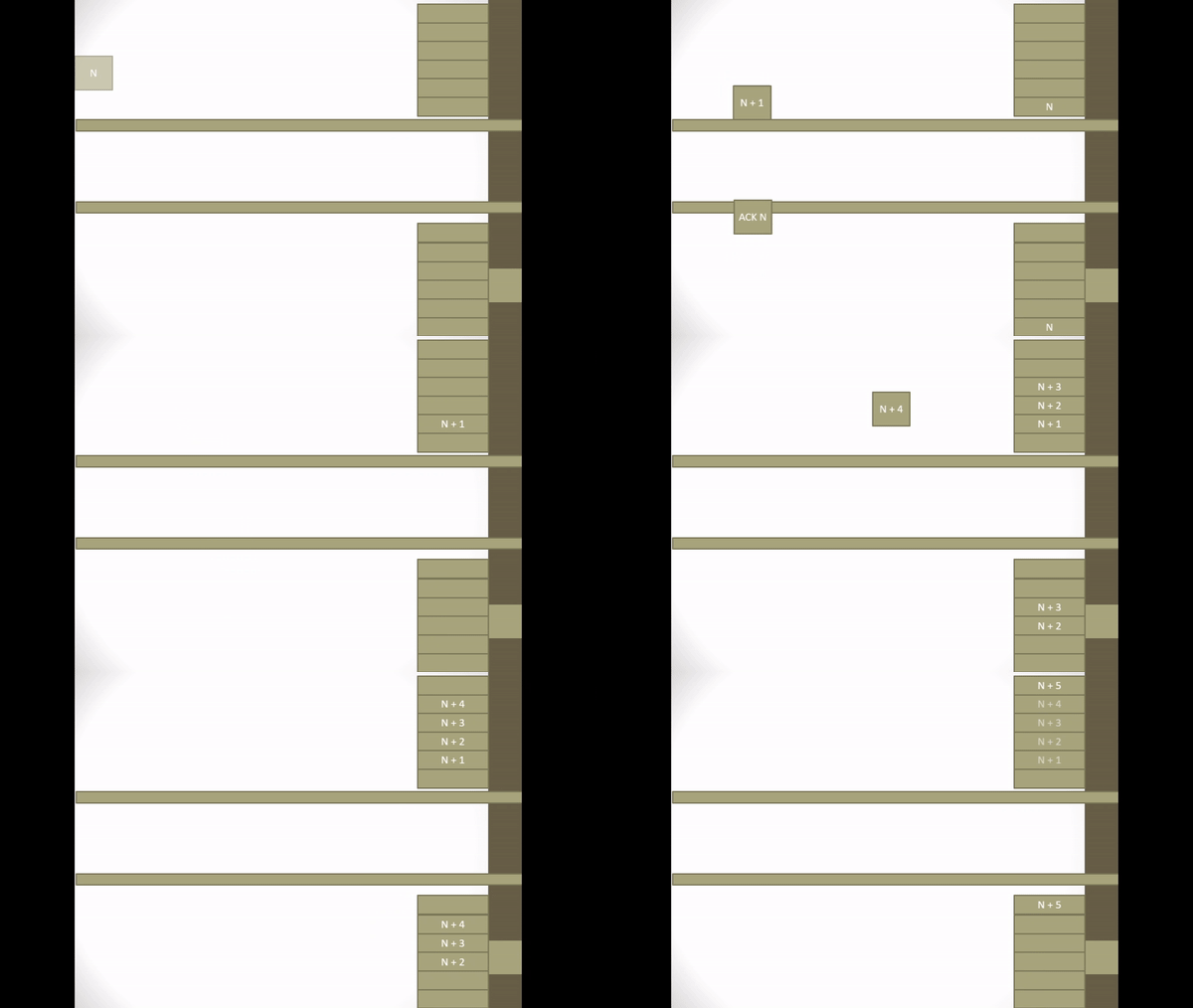
Figure 2.5 Explicit Request Effect Correct Operation
- Initially an ACK frame states that all frames in the retransmission list have been received including I-frames with the sequence number owned by the ACK
- Assume I-frame N + 1 is broken.
- S returns an ACK frame for I-frame N
- When S receives an I-frame N + 2 S notices that I-frame N + 1 is missing so S sends a NAK frame containing the identifier for the missing I-frame N + 1.
- In receiving NAK N + 1, P translates NAK N + 1 and at that time S is still waiting for I-frame N + 1 so P retransmits I-frame N + 1.
- When S sends a NAK frame, S enters a retransmission state.
- When in retransmission state the ACK frame returns are delayed.
- On I-frame reception, N + 1 S leaves the retransmission state and continues to return the ACK frame.
- N + 4 acknowledges that all frames up to I-frame N + 4 have been received correctly including N + 4 frames.
- A timer is used with each NAK frame to ensure that a broken frame will be retransmitted.
Chapter 3 Closing
3.1 Conclusion
The conclusions that can be drawn from this paper are as follows:
- The purpose of error control is to deliver error-free frames in the correct order to the network layer. The technique commonly used for error control is based on two functions, namely: Error detection and Automatic Repeat Request (ARQ).
- By using the selective repeat method, data frames can be sent with a high level of efficiency because if an error occurs during transmission, only the frame that has an error will be retransmitted so that it can reduce the number of frames being transmitted. In contrast to the go back N method, which retransmits the frame starting from the frame where the error occurs to the next frame.
- But if we use the selective repeat method, we need more storage capacity to store the retransmission state and receive lists. In addition, special software is also needed to sort the frames that have been received at the receiver.
3.2 Suggestion
After the authors have made this assignment, the suggestions the authors can suggest are, in sending data packets over a certain medium, there will always be a difference between the sent signal and the received signal. This difference can result in an error or error in the data packet sent so that the data cannot be read properly by the recipient. To avoid errors or errors in the data packet sent, error detection, error correction, and error control are required. So the reader should be able to recognize and know the errors that often occur in a data communication.
Bibliography
- ….., 2008. Laporan Selective Repeat. Avalaible in http://www.scribd.com/doc/23302439/laporan-selektif-repeat (Access 20 April 2012).
- ….., 2008. Makalah Data Link Layer. Avalaible in http://www.scribd.com/doc/24613367/Makalah-Data-Link-Layer (Access 20 April 2012).
- ….., 2011. Tugas Komunikasi Data : Teknik Encoding, Pendeteksi Error, Automatic Repeat Request (ARQ). Avalaible in http://catatan-yushiku.blogspot.com/2011/01/tugas-komunikasi-data-teknik-encoding.html (Access 20 April 2012).
- ….., 2012. Selective_Repeat_ARQ. Avalaible in http://en.wikipedia.org/wiki/Selective_Repeat_ARQ (Access 20 April 2012).
Mirror
- https://www.publish0x.com/fajar-purnama-academics/assignment-about-flow-control-and-selective-repeat-arq-xvwelpr?a=4oeEw0Yb0B&tid=github
- https://0fajarpurnama0.github.io/bachelor/2020/12/02/assignment-flow-control-error-and-selective-repeat-arq
- https://0fajarpurnama0.medium.com/assignment-about-flow-control-and-selective-repeat-arq-7f417e5cb5db
- https://hicc.cs.kumamoto-u.ac.jp/~fajar/bachelor/assignment-flow-control-error-and-selective-repeat-arq
- https://blurt.buzz/blurtech/@fajar.purnama/assignment-about-flow-control-and-selective-repeat-arq?referral=fajar.purnama
- https://0darkking0.blogspot.com/2020/12/assignment-about-flow-control-and.html
- https://hive.blog/technology/@fajar.purnama/assignment-about-flow-control-and-selective-repeat-arq?ref=fajar.purnama
- https://0fajarpurnama0.cloudaccess.host/index.php/9-fajar-purnama-academics/130-assignment-about-flow-control-and-selective-repeat-arq
- https://steemit.com/technology/@fajar.purnama/assignment-about-flow-control-and-selective-repeat-arq?r=fajar.purnama
- http://0fajarpurnama0.weebly.com/blog/assignment-about-flow-control-and-selective-repeat-arq
- https://0fajarpurnama0.wixsite.com/0fajarpurnama0/post/assignment-about-flow-control-and-selective-repeat-arq
- https://read.cash/@FajarPurnama/assignment-about-flow-control-and-selective-repeat-arq-e52037f7
- https://www.uptrennd.com/post-detail/assignment-about-flow-control-and-selective-repeat-arq~ODI0ODA0
%20dan%20saat%20terjadi%20kehilangan%20paket%20dan%20terjadi%20kesalahan%20(b).PNG)